


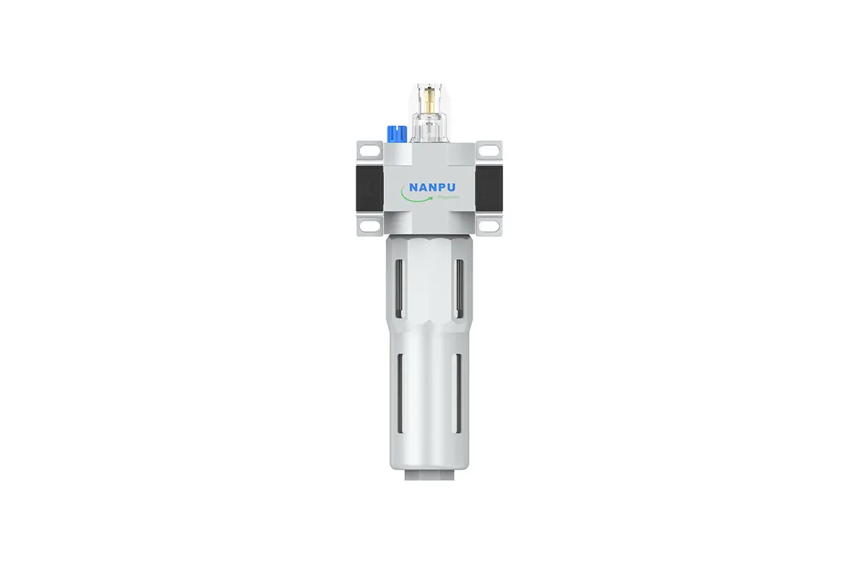

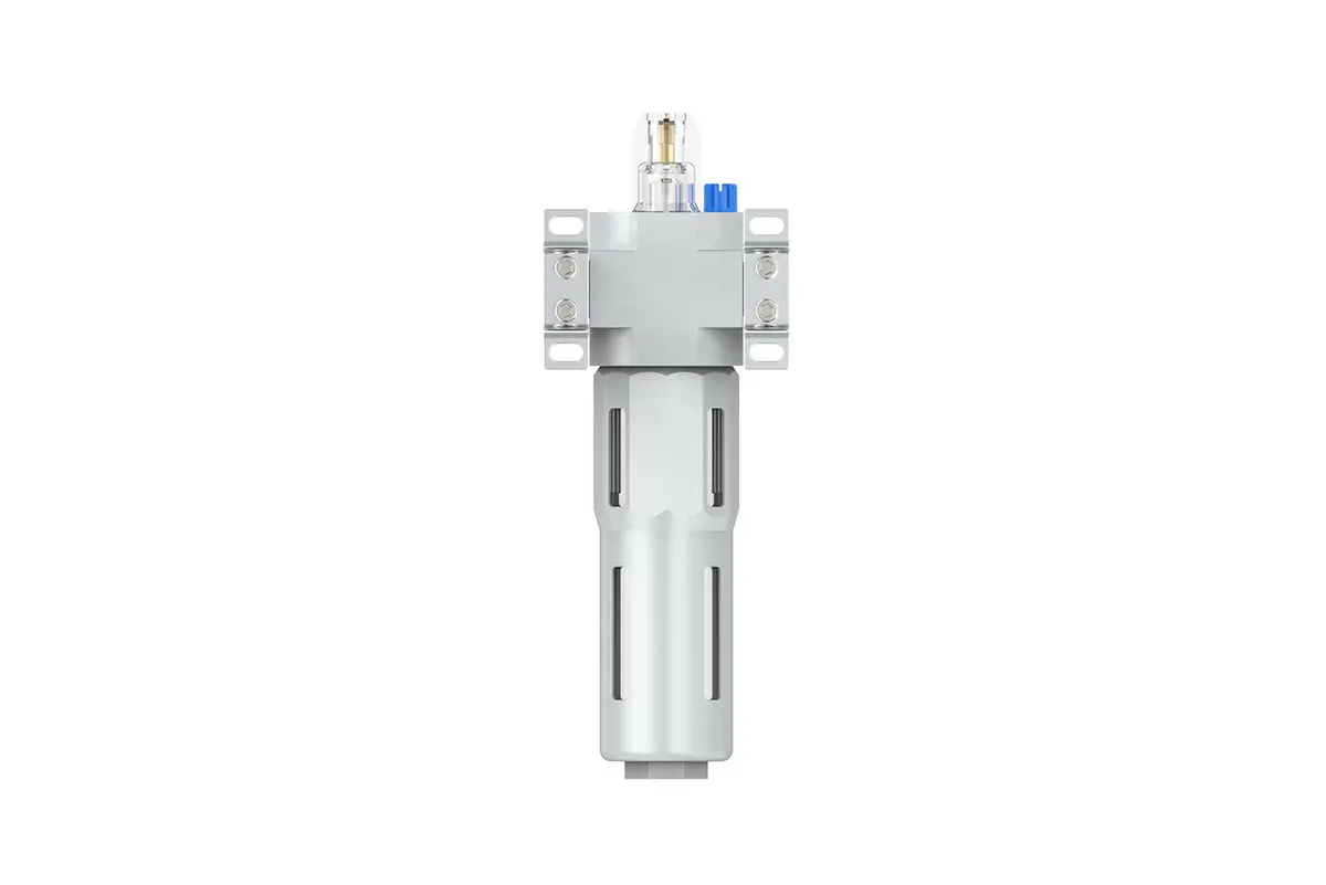
LOE-1/4 3/8MINI,LOE-3/8-1/2-MIDI AluminiumZinc Alloy AR Air Lubricator
description1
LOE-1/4 3/8-MINI,LOE-3/8 1/2-MIDI Aluminium/Zinc Alloy AR Air Lubricator
LOE-1/4 3/8-MINI,LOE-3/8 1/2-MIDI Aluminium/Zinc Alloy AR Air Lubricator
NANPULOE-1/4 3/8-MINI,LOE-3/8 1/2-MIDI
| LOE | 1/4" | MINI | BSP |
| Series Number | Port Size | Body Size | Thread Type |
| 1/4" | MINI | BSP | |
| 3/8" | MIDI | NPT | |
| 1/2" | PT |
NANPUTechnical Specifications
| Model | Specification |
| (L/min)/Rated Flow Rate | |
| LOE-1/4-MINI | 1000 |
| LOE-3/8-MINI | 1200 |
| LOE-3/8-MIDI | 2000 |
| LOE-1/2-MIDI | 2600 |
| Max Input Pressure | 1.6Mpa{16.32kgf/cm²} 232Psi |
| Max Operating Pressure | 1.2Mpa{12.24kgf/cm²} 174Psi |
| Temperature Range | 5~60℃ |
| Pressure Range | LOE1/4~1/2:0.05~1.2Mpa(0.51~12.24kgf/cm²) |
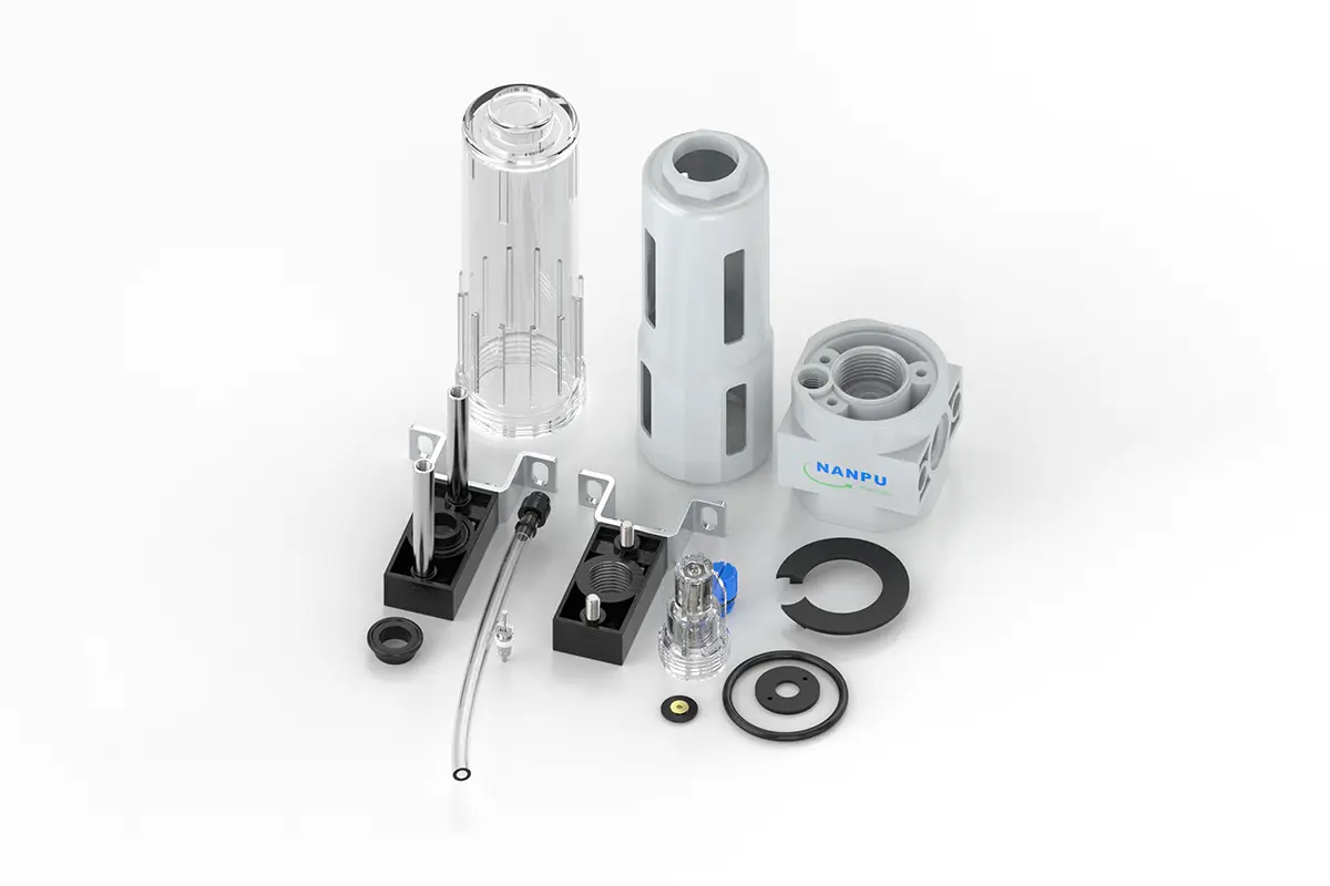
| Bowl Material | Polycarbonate |
| Suggested Oil | Turbine Oil No. 1 ISO-VG32 |
All calibration units must be carefully engineered and assembled to fully comply with the specified maximum flow rate requirements. Strict adherence to these specifications is critical not only for ensuring optimal system performance but also for maintaining long-term reliability and efficiency. Any deviation from the maximum flow standards may lead to subpar operation, increased energy consumption, and potential system failures.
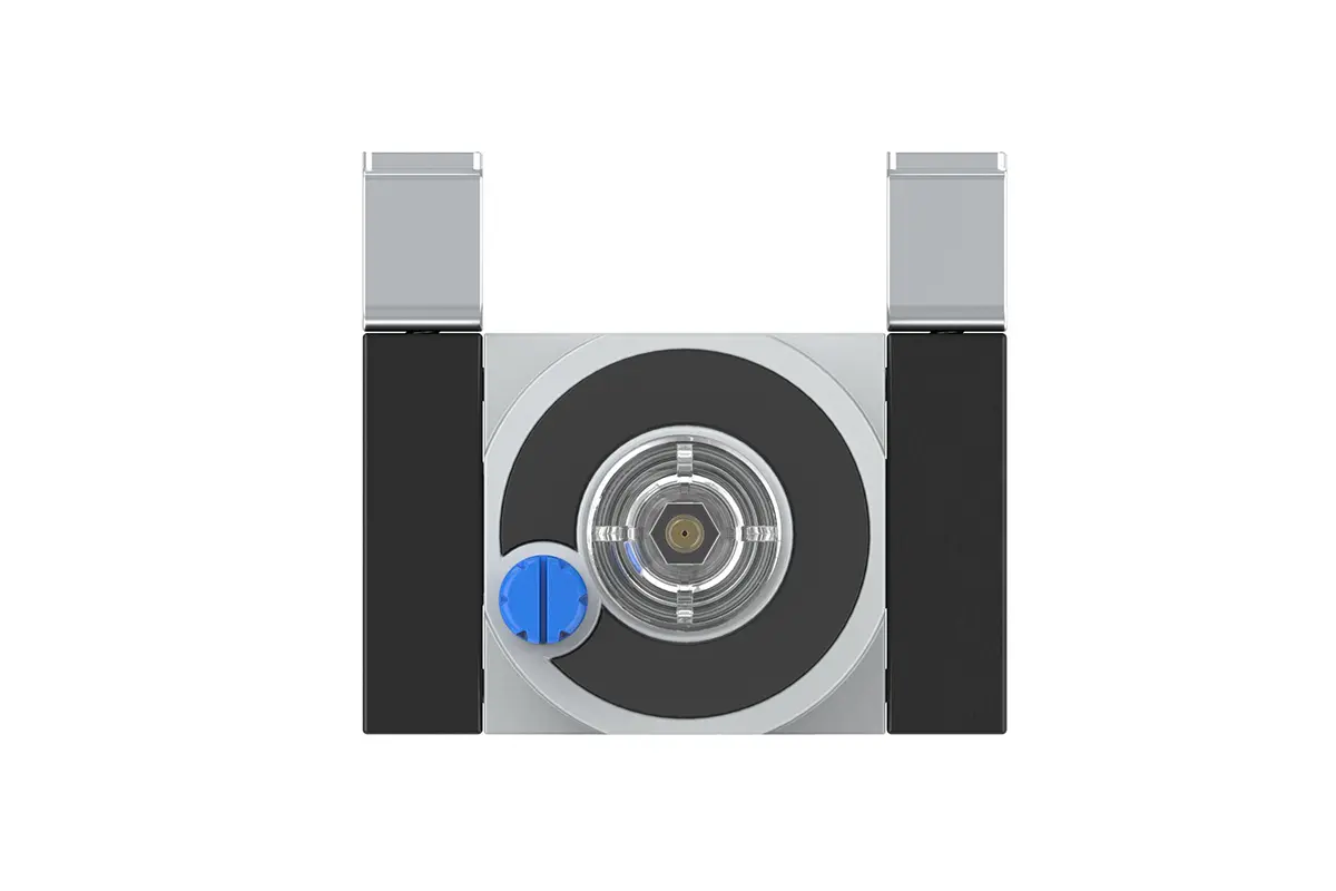
To adjust the oil intake rate of the lubrication system, precisely manipulate the needle valve. Turning the needle valve clockwise (as indicated by the "+" symbol) progressively increases the valve orifice size, allowing a larger volume of oil to enter the system and thereby accelerating the oil intake rate. This adjustment is ideal for high-load operating conditions.
Conversely, turning the needle valve counterclockwise (corresponding to the "-" direction) gradually reduces the orifice size, resulting in a decreased oil intake rate. Sustained rotation in this direction will eventually halt oil flow entirely, enabling precise regulation of the lubrication process.
To properly perform the oil-filling procedure, rotate the oil-filling screw clockwise to expose the lubricant insertion port. It is critical to adhere to the provided safety and operational guidelines by ensuring that the volume of oil added does not exceed 80% of the bowl’s total capacity. Overfilling with oil may lead to spills during system operation, potential contamination of adjacent components, and interference with the normal functioning of the lubrication system. Upon completion of oil-filling, use an appropriately torque-rated tool to securely tighten the oil-filling screw, re-establishing the system’s airtight seal and preventing any lubricant leakage.