


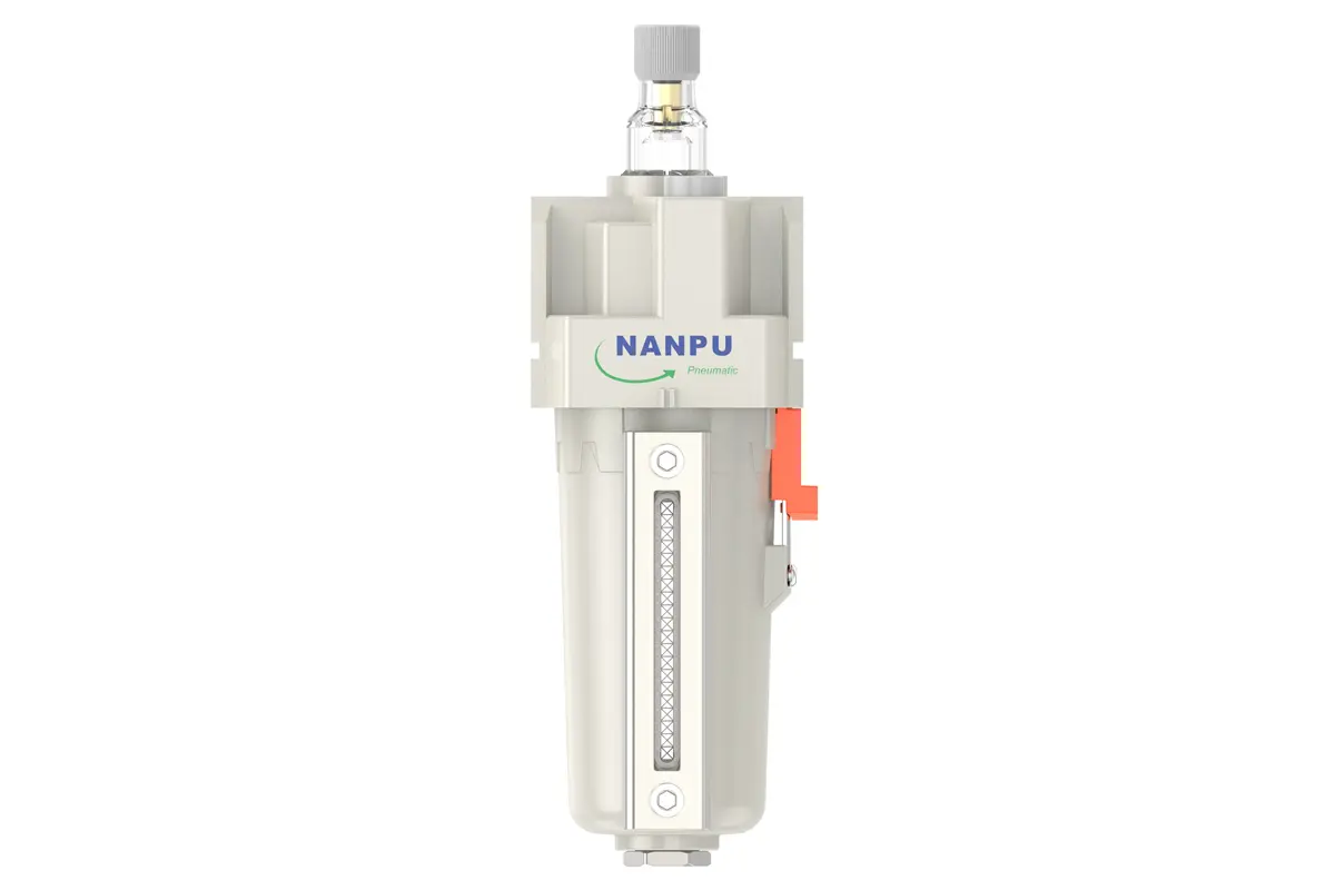
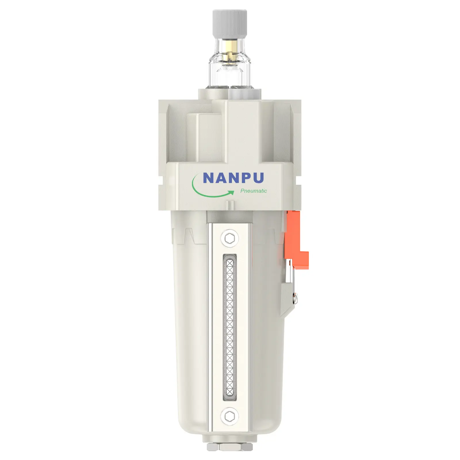
TL3000-02/03 TL4000-04/06 1/4" 3/8" 1/2" Aluminium TL Air Lubricator
description1

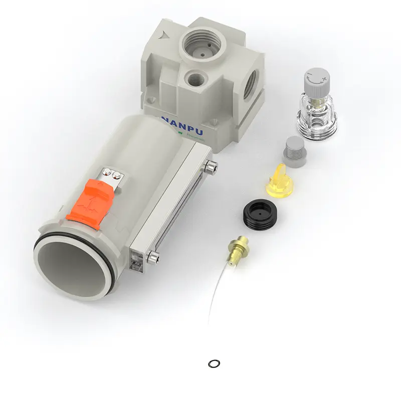
TL3000-02/03 TL4000-04/06 1/4" 3/8" 1/2" Aluminium TL Air Lubricator
NANPUTL3000-02/03 TL4000-04/06 1/4" 3/8" 1/2" Aluminium TL Air Lubricator
| TW | 3000 | BSP | D | |
| Series Number | Port Size | Thread Type | Drainage Method | |
| 3000 | 02:1/4" 03:3/8" | BSP | Blank: Differential Pressure Drain | |
| 4000 | 04:1/2" 06:3/4" | NPT | A: Manual Drain |
NANPUTechnical Specifications
| Technical Specifications | ||
| Max Input Pressure | 2.0Mpa{20.39kgf/cm²} 290Psi | |
| Max Operating Pressure | 1.8Mpa{18.35kgf/cm²} 261Psi | |
| Temperature Range | 5~60℃ | |
| Body Material | Aluminium | |
| Bowl Guard | YES | |
| Suggested Oil | Turbine Oil No. 1 ISO-VG32 |
| Model | Specification |
| (L/min)/Rated Flow Rate | |
| TL3000-02 | 1000 |
| TL3000-03 | 1200 |
| TL4000-04 | 2000 |
| TL4000-06 | 2600 |
| Product Benefits |
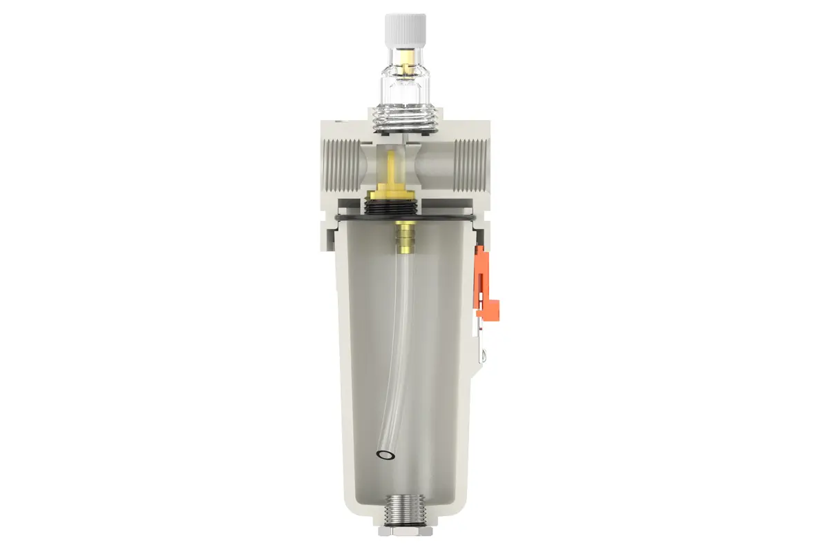
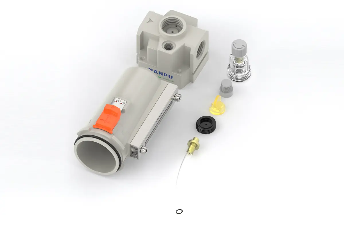
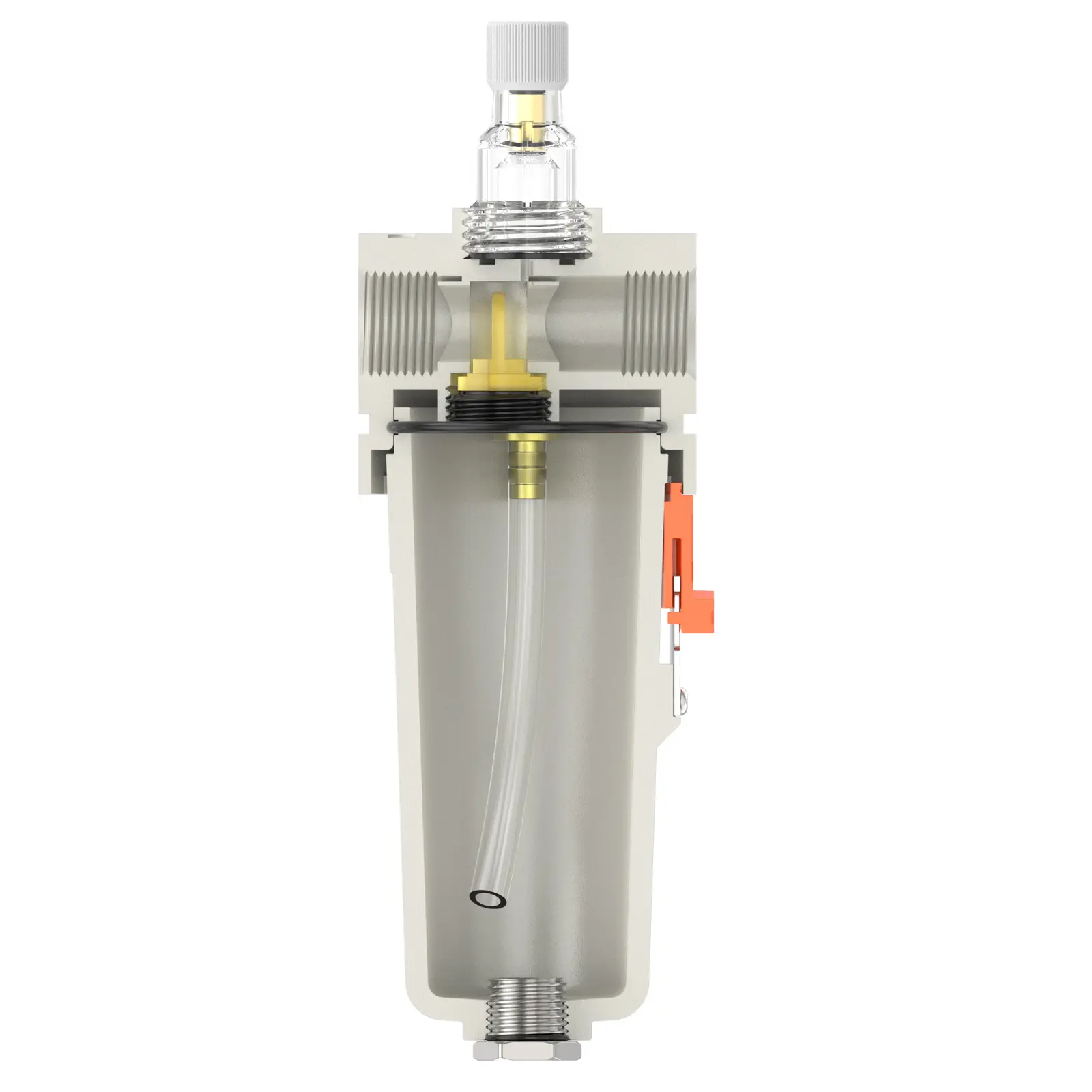
| Almost all pneumatic tools perform better when lubricated with oil.Injecting an oil mist into the air-stream which powers them can continuously lubricate valves,cylinders,and air motors for proper operation and long service life. |
All calibration units must be carefully engineered and assembled to fully comply with the specified maximum flow rate requirements. Strict adherence to these specifications is critical not only for ensuring optimal system performance but also for maintaining long-term reliability and efficiency. Any deviation from the maximum flow standards may lead to subpar operation, increased energy consumption, and potential system failures.
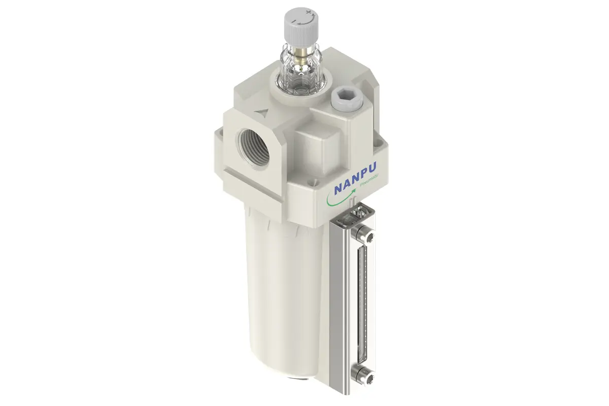
To regulate the oil feed rate of the lubrication system, adjust the needle valve with precision. Clockwise rotation of the needle valve (as denoted by the "+" indicator) progressively enlarges the valve orifice, facilitating a higher volume of oil ingress into the system and thereby increasing the oil feed rate. This adjustment is particularly suitable for high-load operational scenarios.
Conversely, counterclockwise rotation of the needle valve (corresponding to the "-" direction) gradually reduces the orifice diameter, leading to a diminished oil feed rate. Sustained rotation in this direction will ultimately arrest oil flow, enabling fine-grained control over the lubrication process.
To execute the oil-filling procedure correctly, rotate the oil-filling screw clockwise to uncover the lubricant injection port. It is imperative to comply with the provided safety and operational protocols by ensuring the oil volume added does not exceed 80% of the bowl's total capacity. Overfilling the bowl may result in oil spillage during system operation, potential contamination of adjacent components, and disruption to the lubrication system's normal functionality. After completing the oil-filling, use a torque-rated tool to fasten the oil-filling screw securely, restoring the system's airtight seal and preventing any lubricant leakage.